Iranian Classification Society Rules

< Previous | Contents | Next >
Section 2 Stability
201. General
1. Intact stability are to be in accordance with this section in addition to Ch 3, Sec 1. However, for ships specifically approved by the Society, these requirements may be waived.
2. Stability is to be considered especially to the ships that have specially designated operations.
3. Stability calculations and corresponding information for the Master are to be submitted for review and approval.
4. The submission of evidence showing approval by an Administration of stability of the vessel for the towing operations in accordance with a recognized standard may be acceptable.
202. Intact Stability Guidelines for Anchor Handling
1. Additional Intact Stability Criteria
(1) Intact Stability
For vessels that are used for anchor handling and which at the same time are utilizing their towing capacity and/or tractive power of the winches, calculations are to be made showing the acceptable vertical and horizontal transverse force/tension to which the vessel can be exposed. The calculations are to consider the most unfavorable conditions for vertical and transverse force/tension and as a minimum include the following:
(a) Calculations are to be made for the maximum acceptable tension in wire/chain, including the maximum acceptable transverse force/tension that can be accepted in order for the vessel’s maximum heeling to be limited to one of the following angles, whichever occurs first:
(i) Heeling angle equivalent to a GZ value equal to 50% of GZ max
(ii) The angle which results in water on working deck when the deck is calculated as flat
(iii) 15 degrees
(b) The heeling moment is to be calculated as the total effect of the horizontal and vertical transverse components of force/tension in the wire or the chain. The torque arm of the hori- zontal components shall be calculated as the distance from the height of the work deck at the guide pins to the center of main propulsion propeller or to center of stern side propeller if this projects deeper. The torque arm of the vertical components is to be calculated from the centre of the outer edge of the stern roller and with a vertical straining point on the upper edge of the stern roller.
(2) Loading Conditions
The following loading conditions intended for anchor handling are to be examined in the Trim and Stability Booklet:
(a) Vessel at the maximum Load Line draft, with full stores and fuel and fully loaded with all
liquid above above
and dry cargo distributed below deck and with remaining deadweight distributed as deck weight (anchors, chain, etc., specified by weight, LCG, VCG and total height deck) corresponding to the worst service departure condition in which all the relevant
stability criteria are met.
(b) Vessel with 10% stores and fuel and fully loaded cargoes of (a) above, arrival condition.
(c) Vessel at the maximum Load Line draft, with full stores, a full set of rig anchors on deck to be deployed during single trip (and rig chains, if appropriate) and fuel loaded to the maximum deadweight, corresponding to the worst service departure condition in which all the relevant stability criteria are met.
(d) Vessel with 10% stores and fuel and fully loaded cargoes of (c) above, arrival condition.
(e) Vessel in worst anticipated operating condition.
These conditions are to include the following items:
(i) The loads on the deck (including the weight of anchors, chains and lines) and winch reels (loaded with heaviest possible line types).
(ii) The vertical force from the tension, upon which calculations of trim and curve for righting arm are based.
(iii) The weight of the anchors and lines.
(iv) The righting free surface of
arm curve (GZ curve) is to be plotted using the VCG corrected for the all slack tanks, including any roll reduction tanks in use. Consideration is
20 Guidance for Offshore Support Vessels 2015
![]()
to be given to fuel oil and ing the operations.
(v) If the vessel is fitted with
fresh water used as well as any ballast water necessary dur-
rig chain locker(s) below the main deck, the opening(s) is to
be considered as a downflooding point for the stability calculations in 201.
(vi) If the vessel is fitted with open rig chain lockers on the main deck, effective means to drain these lockers are to be provided. If not, the lockers shall be considered flooded and the appropriate free surface effects included in all stability calculations.
(3) Stability Guidance for the Master
The trim and stability booklet, required by Ch 3, 102, is to include the following guidance: (a)Information stating the maximum force/tension in wire or chain, as well as corresponding lateral
point of direction according to the calculations, is to be provided in the trim and sta- bility booklet and be displayed next to the control desk or at another location where the nav- igator on duty easily can see the information from his command post.
(b) The displayed information is to be in the form of simple sketches showing the vessel’s righting moment/arm curves in addition to a table stating the relevant combinations of
force/tension and point of direction which gives the maximum acceptable heeling moment.
(c) Any tank restrictions (i.e. ballast tank and/or roll reduction tank usage, fuel oil burn off se- quences, etc.) determined by the stability calculations.
During anchor handling operations, all weather-tight access and emergency hatches, and doors on
the work deck, are to be kept closed, except when actually being used for transit under safe conditions.
203 Intact Stability Guidelines for Towing
1. General
The intact stability of each vessel receiving a towing notation is to be evaluated for the applicable loading conditions indicated in Ch 3, 102. for compliance with the intact stability criteria in 2. and the results are to be submitted for review.
2. Intact Stability Criteria
(1) Towing Operating
The heeling arm curve due to towline pull should be calculated in accordance with 3. The area of the residual dynamic stability (area between righting and heeling arm curves beyond the an- gle of the first intercept) up to an angle of heel of 40° beyond the angle of the first intercept (A1 + A2), or the angle of downflooding, if this angle is less than 40° beyond the angle of the first intercept (A1), should not be less than 0.09 meter-radians. (See Fig 5.1)
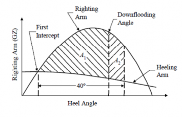
Fig 5.1 Righting Arm and Heeling Arm Curves
3. Heeling Arm Curve
The towline pull force should be calculated using the corresponding percentage of the maximum bollard pull force, depending on the type of propulsion (Table 5.1), at right angles to the vessel's fore and aft axis. The heeling moment due to towline pull should be calculated by multiplying the
Guidance for Offshore Support Vessels 2015 21
![]()
towline pull force by the distance from the top of the towing bitt to the intersection of propeller shaft centerline and rudder axis. The resultant moment should be converted to a heeling arm and plotted on the same graph as the righting arm/GZ curve (corrected for free surface). The heeling arm curve can be taken to vary with the cosine of the heeling angle.
The bollard pull force shall be derived from the actual test. For the purposes of preliminary stabil- ity evaluations prior to the bollard pull test, the bollard pull force may be estimated, depending on
the type of propulsion and shaft power (SHP), as per Table 5.1.
Table 5.1 Towline Pull Force
Type of Propulsion | Towline Pull Force as percentage of Max Bollard Pull Force | Bollard Pull Force estimate based on shaft power kN/kW |
Twin screw with open propellers, or other types not listed below | 50% | 5029 |
Twin screw with open propellers and flank rudders | 50% | 5029 |
Twin screw with conventional non-movable nozzles | 50% | 5867 |
Water Tractor Tug with twin pro- peller Z-drives (steerable propellers with nozzles) | 50% | 5867 |
Water Tractor with twin cycloidal propellers (vertical axis) | 50% | 5029 |
4. Stability Guidance for the Master
The Master of the vessel should receive information in the Trim and Stability Booklet regarding cargo and/or ballast limitations, list of protected flooding openings that need to be kept closed, wind and/or wave restrictions, etc., necessary to ensure that the stability is in compliance with the criteria given in the above 2.
If any loading condition requires water ballast for compliance with the criteria in the above 2, the quantity and disposition should be stated in the guidance to the Master.